Semiconductor
Ceramic End Effectors, Vacuum Chucks and Paddles
Every wafer is moved by a robot, and the point of contact is almost always ceramic. The material is only half the decision — flatness, edge geometry.
Read this guideFrom wafer handling to etch, CVD and CMP, technical ceramics are doing a job that metal, plastic and quartz cannot. Here is what sits where, and which material belongs in each position.
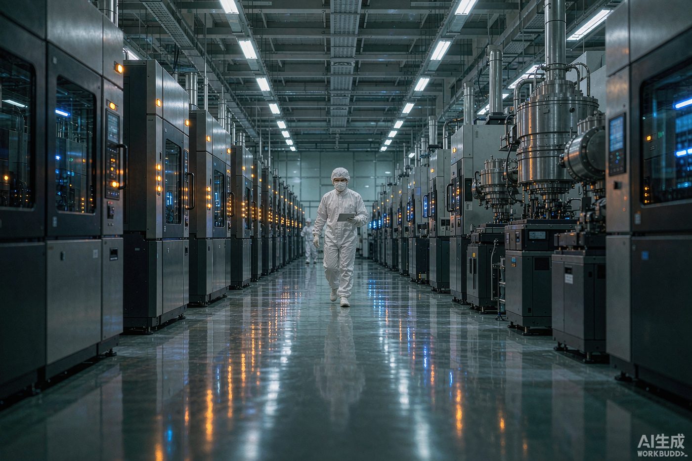
In a wafer fab, ceramics solve three problems that metals, polymers and quartz cannot solve at the same time: they do not contaminate the wafer, they survive plasma and high temperature, and they hold dimensional stability under thermal cycling.
Alumina covers most insulating and chamber positions, aluminum nitride covers thermal and electrostatic positions, silicon carbide covers the most aggressive plasma and high-temperature positions, and zirconia covers wear and fluid-handling positions. Most process tools use two or three of these at once.
Four requirements drive almost every ceramic part in a fab:
Every wafer that enters a tool is moved by a robot, and the point of contact is almost always ceramic.
Our separate guide covers end effector, chuck and paddle design in more depth.
Etch chambers are the most hostile ceramic environment in a fab. The plasma physically bombards surfaces, chemically attacks them, and deposits re-sputtered material on the wafer.
| Part | Typical material | Why |
|---|---|---|
| Focus ring | High-purity SiC (increasingly), alumina, Y2O3-coated | Shapes the plasma sheath at the wafer edge; wears fastest of all ceramic parts |
| Chamber liner / shield | Alumina 99.7%–99.8%, SiC | Protects the metal chamber wall and controls the chemistry seen by the wafer |
| Showerhead / gas distribution | Alumina, SiC, SiC-coated graphite | Uniform gas delivery plus plasma exposure; must not sputter metals |
| Insulating rings and sleeves | Alumina 99.7%–99.8% | Hold off RF and DC potential while sitting in the plasma |
| ESC body | AlN, alumina | Clamp the wafer electrostatically and control its temperature |
| Heater core | AlN | High thermal conductivity, insulating, integrated heater layers |
The material choice here is economic as much as technical: a focus ring that costs more but lasts three times as long and releases less aluminium is usually the cheaper part over a year. We wrote a longer piece on why focus rings and liners move from alumina to SiC.
Deposition and furnace positions combine high temperature with aggressive chemistry and, often, thermal shock.
Chemical mechanical planarisation is a wet, abrasive environment with tight flatness requirements.
Outside the process chamber, ceramic substrates keep the tool and its electronics alive.
Four things need to be on the drawing, in addition to geometry:
Our RFQ checklist turns this into a form you can hand to an internal engineer.
For semiconductor work, the ability to grind and inspect is often more important than the ability to press and sinter. Look for diamond grinding and lapping in-house, CMM inspection, a defined cleaning process, and an engineering team that will push back when a drawing is not manufacturable rather than quoting it and delivering something approximate.
Dolphin Advanced Ceramic runs powder formulation through to final inspection in Zibo, Shandong — including CIP and dry-bag pressing, sintering to 1800 °C, diamond grinding to ±0.005 mm and metallization. Send us a drawing and we will tell you straight away whether we can make it.
Alumina, in high-purity grades. It covers the largest number of positions — insulating rings, chamber liners, end effectors, chuck inserts, furnace tubes and standoffs — because it combines insulation, plasma resistance and acceptable cost. Silicon carbide is the fastest-growing material, driven by plasma-facing parts.
Because contamination is measured against a nanometre-scale device. Impurities such as sodium, potassium, iron and copper in a ceramic can migrate into a wafer or deposit on it as particles, causing electrical leakage and killer defects. That is why 99.7% and 99.8% grades exist and why they are specified for wafer-exposed positions.
Yes. Prototype and qualification batches are a normal part of our work — customers need to test fit, particle performance and life on real hardware before committing to production volumes. Unit cost is higher at prototype quantity and falls significantly once tooling and process parameters are fixed.
Typically 4–8 weeks from drawing release for a first article, depending on geometry, grinding complexity and whether new tooling is required. Repeat orders on established parts usually run considerably faster. We confirm lead time with the quotation.
Send us the drawing, the grade and the quantity. Our engineers reply with a manufacturability review and a quotation within 24 hours.